The brake switch
The brake switch on the later MGBs is in a pretty awful position behind the pedal box. We managed to test ours in-situ using a multi-meter, so we knew it worked, but we had to remove it to re-fit the wiring. Luckily a little bit of effort on the lock-nut released it without damage.
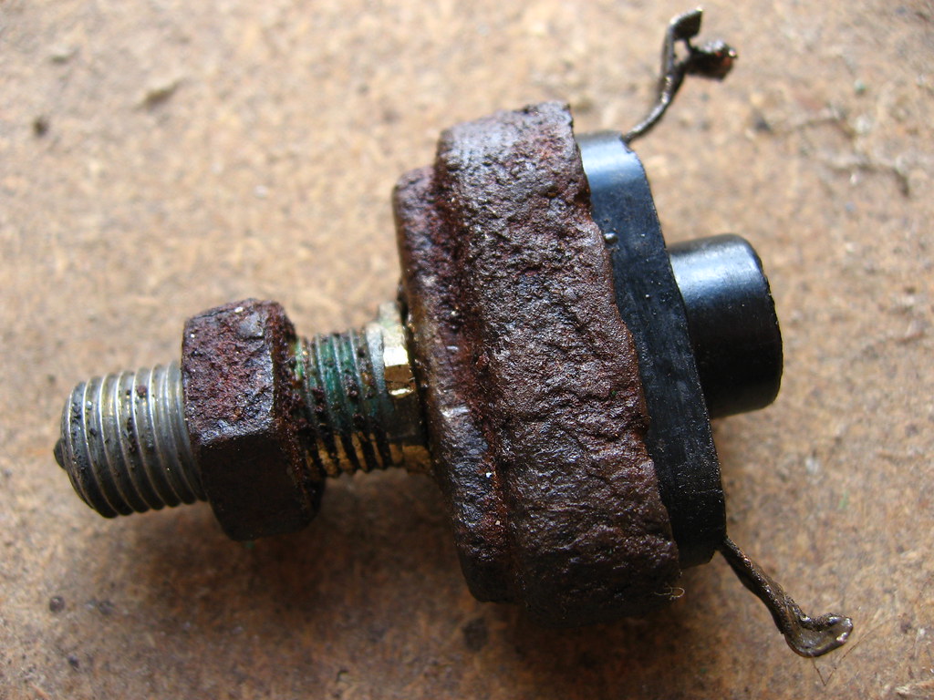
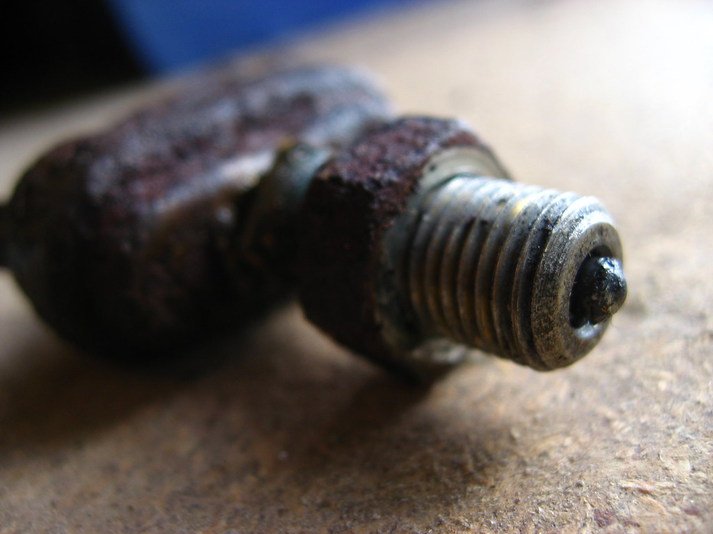
It works on a basic plunger, the screw thread acting as the cylinder with the plunger inside. As the pedal is depressed the top of the arm pushes the end of the thread where the plunger sticks out (fig 3).
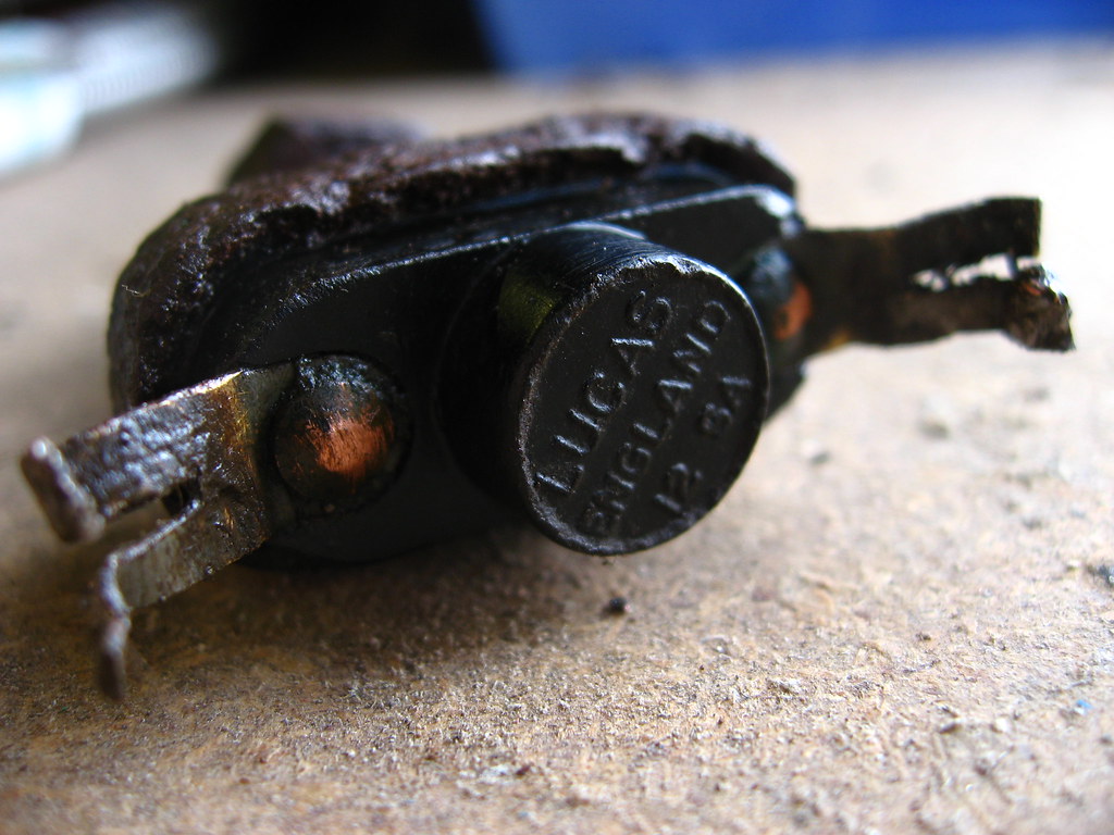
Amazingly, despite the age and outward condition of the switch it works perfectly. We had to do a bit of rewiring as the mice had chewed through it all. The three wires which come out of the harness by the pedal box (fig 4) come together at the switch. Two of them are for the switch itself and the third draws a feed off those to power the washer pump. The connections at the switch are basic fold-over crimps (fig 2) and hold the wire pretty well, especially as once the bundle is tucked away it won't move.
The lock-nut sits on the thread and holds the plunger at the right distance from the top of the pedal. Turning the nut moves the plunger towards or away from the pedal and so adjusts the point where the lights come on.
When you're testing this, remember to take the handbrake off as otherwise you won't get a feed to the lights.